Hello Whipple owners...
I was disappointed that Whipple did not relocate the IAT sensor to after the compressor. As you know, monitoring air temperature before the compressor underestimates the temperature of the air entering the cylinder, and could result in detonation on hot days if not compensated for somehow in the tune. The right way to solve the problem is to drill and tap a 3/8"-NPT hole in the intake manifold and install the DY754 IAT sensor. However, this requires removing the blower, which is a PITA. When I eventually swap the engine internals, I will do this. But I wanted a short term solution for now to ease my mind about the intake air temperature. So here's what I did.
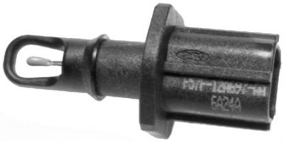
Image 1 - Bought a DY735 plastic push-in type of IAT sensor, along with the connector, WPT420.
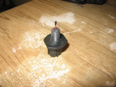
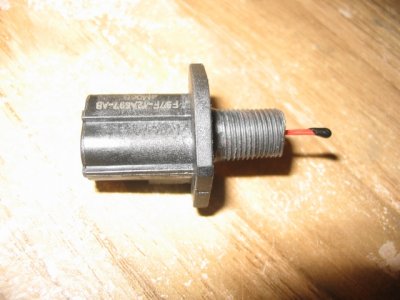
Image 2 & 3 - Used a Dremel tool to remove material until the OD of the sensor was 0.405" diameter. Bought a 1/8"-NPT die at the local hardware store, and threaded the shaft.
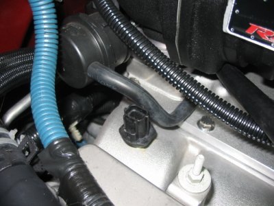
Image 4 - Threaded the sensor into the existing 1/8"-NPT hole in the intake manifold. Used Teflon sealant.
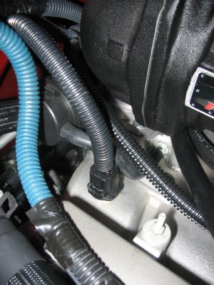
Image 5 - Cut the wires to the temperature sensor in the MAF sensor, and re-route to the newly installed IAT sensor.
I confirmed that the DY735 reads exactly the same as the MAF sensor prior to proceeding. I've been driving around for 6 months now taking data, and the numbers I'm getting all make sense.
I moved my boost gauge monitor pickup to the fuel rail pressure sensor vacuum hose. This works well, since that line senses pressure after the compressor.
Ultimately I'd like to replace the plastic sensor with the metal one, but the plastic was very hard, and feels strong enough to last the life of the engine anyway.
I did all of this with common hand tools.
I was disappointed that Whipple did not relocate the IAT sensor to after the compressor. As you know, monitoring air temperature before the compressor underestimates the temperature of the air entering the cylinder, and could result in detonation on hot days if not compensated for somehow in the tune. The right way to solve the problem is to drill and tap a 3/8"-NPT hole in the intake manifold and install the DY754 IAT sensor. However, this requires removing the blower, which is a PITA. When I eventually swap the engine internals, I will do this. But I wanted a short term solution for now to ease my mind about the intake air temperature. So here's what I did.
Image 1 - Bought a DY735 plastic push-in type of IAT sensor, along with the connector, WPT420.
Image 2 & 3 - Used a Dremel tool to remove material until the OD of the sensor was 0.405" diameter. Bought a 1/8"-NPT die at the local hardware store, and threaded the shaft.
Image 4 - Threaded the sensor into the existing 1/8"-NPT hole in the intake manifold. Used Teflon sealant.
Image 5 - Cut the wires to the temperature sensor in the MAF sensor, and re-route to the newly installed IAT sensor.
I confirmed that the DY735 reads exactly the same as the MAF sensor prior to proceeding. I've been driving around for 6 months now taking data, and the numbers I'm getting all make sense.
I moved my boost gauge monitor pickup to the fuel rail pressure sensor vacuum hose. This works well, since that line senses pressure after the compressor.
Ultimately I'd like to replace the plastic sensor with the metal one, but the plastic was very hard, and feels strong enough to last the life of the engine anyway.
I did all of this with common hand tools.
 I had to re-order one from Ford Racing which over writes the 93 octane tune to a 91 octane tune.